Bigger, Faster, Stronger!
The Dobot CR series of collaborative robotic arms have been used to automate many industrial workflows over the years. Whether palletising, welding or assembly, you will find the most optimal solution for your application in the CR series (CR3, CR5, CR7, CR10, CR12, CR16).
However, the industry can be subject to extreme conditions where heavy duty, fast operation and compliance with stringent safety regulations are required.
In response to these needs, Dobot has created the latest generation of its collaborative robotic arms, the CRA series, which incorporates the advantages of cobots and takes their performance parameters to new heights. But what provides the new impetus for a timeless design?
Improved internal architecture and speed
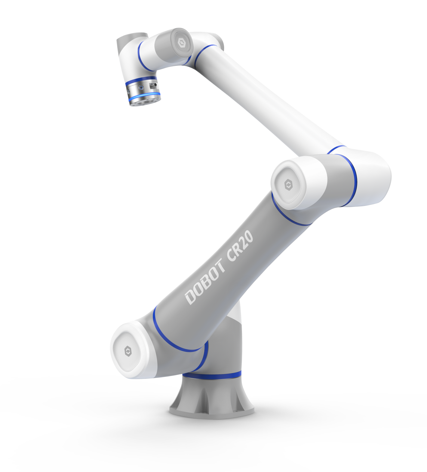
Thanks to its new generation of internal servo motors and innovative dynamic algorithms, the angular speed of the axles has been increased by 25%, while vibration at low speeds has been reduced by 50% compared to the CR series.
Its braking system has been completely redesigned and now uses an electromagnetic system, reducing the previous 10mm stopping distance to less than 1mm! A crowded working environment is no longer a challenge for Dobot's industrial robotic arms, yet you no longer have to worry about the robot harming you or your co-worker.
New control unit, wider range of tasks
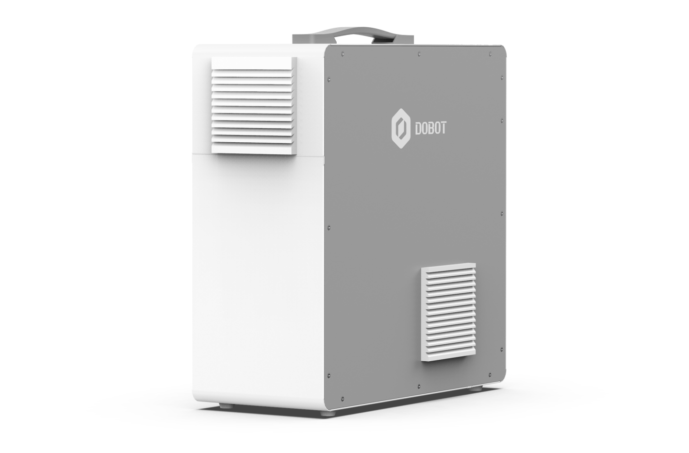
An essential accessory for Dobot's industrial collaborative robot arms is the control unit, which is used to program the robot arm and attach various accessories to it.
The IO interface of the new CC262 controller has been upgraded to 24 pins, and its communication interface has been extended with 1-1 additional Network and USB ports. In addition, the controller has RS485 support, its weight has been reduced by 20%, the number of communication protocols has been doubled and its noise level is 20% lower!
The controller's software runs on version 4.x, which leaves room for continuous development of the DobotStudio Pro IDE (Integrated developer Environment). This makes the user interface even more streamlined, easier to use and faster to understand updates.
New generation, new model
The very first model in the CRA series adds innovative technology and new parameters to the application of cobots.
The CR20A, the largest in the series, is the largest robot arm ever produced by Dobot, with a load capacity of around 20kg and a reach of 1750mm, opening the door to automation! This means that tasks with heavier and larger workpieces are no problem in industrial applications,
While retaining all the advantages of collaborative robotic arms!
Flexible deployment, fast implementation
As with the previous series, the system can be set up in just 20 minutes and ready to use in up to 1 hour.
Easy to access, easy to learn.
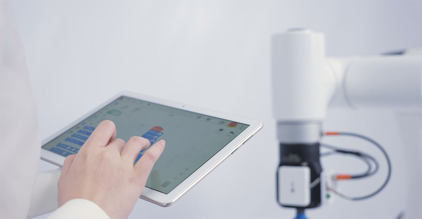
Dobot's software and arithmetic technology make the operation and management of the robotic arm series intelligent and simple. Thanks to software and manual training, you can accurately mimic human movements. No programming skills are required.
Advanced safety system and more
The advantage of collaborative robots is that they are equipped with pressure sensors in the housing, which allow the robot to stop its current work if the pressure exceeds a threshold, and the system will not continue until the pressure is released. With this addition, the efficiency and safety of human-robot work is taken to new levels.
End tools
End tools are the devices that can be mounted on the ends of the robot arms. The DOBOT CRA collaborative robot series is compatible with a wide range of end tools, so it will be able to meet even the most specific needs of your business. Whether it's welding, palletising, loading, bolting, sorting, assembly or quality control, any process can be equipped with vacuum or electronically powered grippers, MODBUS units for communication and automation, or conveyor and visual unit accessories to maximise the robot arm's efficiency.
Parameters
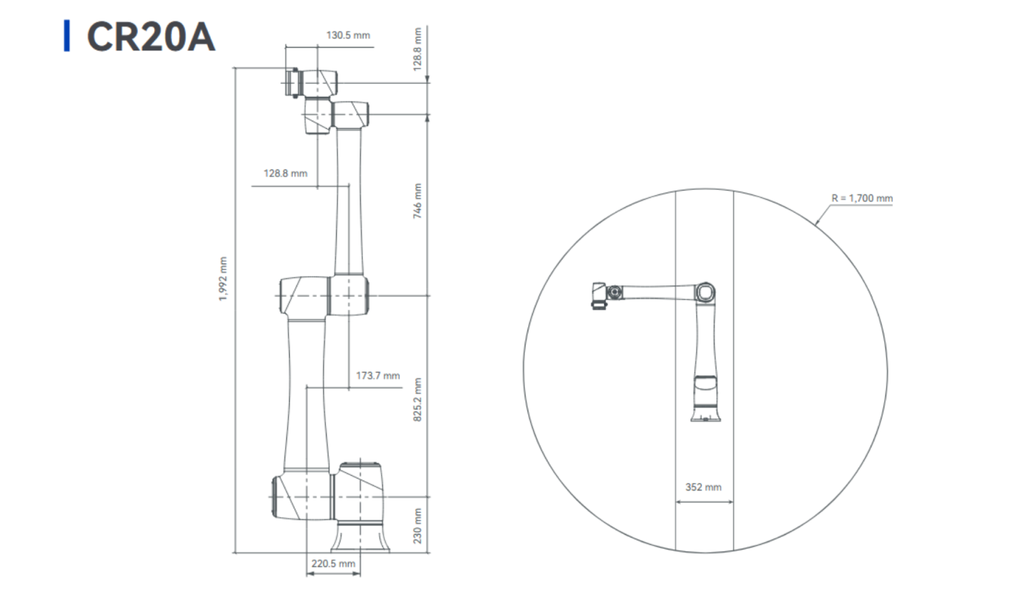
CR20A collaborative robotic arm |
Weight | 70kg |
Max workload | 20kg |
Max Working radius | 1700mm |
Maxi speed of End Tool (TCP) | 2m/s |
Range of Joints | J1 | ±360° |
J2 | ±360° |
J3 | ±165° |
J4 | ±360° |
J5 | ±360° |
J6 | ±360° |
Max speed of Joints | J1/J2 | 120°/s |
J3 | 150°/s |
J4/J5/J6 | 180°/s |
I/O interface | Power connection | 24V, Certified 2A, maximum 3A |
Ports (2) | RS485/AI, |
2x DO |
2x DI |
Repeated accuracy | ±0.1mm |
IP Rating | IP54 |
Noise | ≤ 70 dB |
Working temperature | 0~50°C |
Controller unit connector cable length | 6 m |
Materials | Aluminum, ABS plastic, carbon fibre steel |
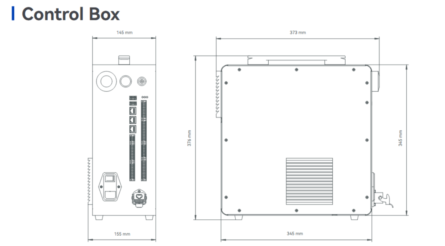
CC262 Control Unit |
Weight | 15kg |
Size (L x H x W) | 400mm x 400mm x 175mm |
Voltage | 100V ~ 240V AC |
IO Voltage | 24V, Max. 3A, Max. 0,5A for each channel |
I/O Ports | DI / DO | 24 channel (NPN and PNP) |
AI / AO2 | 2 channels (in voltage or current mode) |
SI / SO | 10 channels (5 series configurable for security feature) |
Communication interface | Ethernet | 2 (TCP/IP, Modbus TCP, Profinet, Ethernet/IP) |
EtherCAT | Reserved for controlling the robot's external axes |
USB | 2 |
RS485 | 1 (for ModbusRTU communication) |
Operating conditions | Temperature | 0~50°C |
Humidity | 0% - 95% (non-condensing) |
Noise | ≤ 60 dB |
Remote control | Supported |
IP rating | Original: IP20 , Optional: IP54 |
Cooling mode | Fan |
Programming modes | PC, SmartPhone (Android and IOS) |
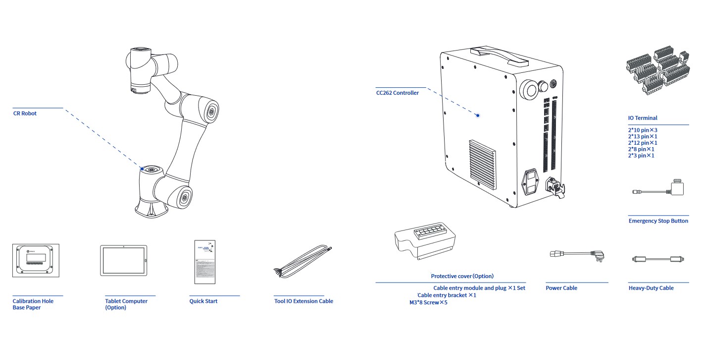
Contents of package
6 axes, 4 movement modes
The robot arm can move from point A to point B by connecting two coordinate points in 4 modes:
Joint Interpolated Motion: the motion can be implemented using GO and MoveJ software, which allows the robot arm to reposition from point A to point B by interpolating the joint angle of the robot arm without taking into account the position of the end tool
Linearly Interpolated Motion: The motion can be implemented by Move, which allows the robot to link the coordinates of point A and point B, looking at the position of the sky, which guides the end tool in a straight line. In the case of linear motion, a distinction can be made between the use of the jump mode, in which the end tool either moves the two coordinate points to their end positions, or applies a rounding off to perform a continuous motion, taking the coordinates of the point into account.
ARC -Circular Interpolated Motion: The robot connects points A and B along an arc by means of an auxiliary point C, thus performing an arc motion taking into account the position of the end tool
Circle - Circular Interpolated Motion: The robot connects points A and B by means of a helper point C and performs its motion by describing a circular shape, taking into account the position of the end tool.
PProgramming can be done in several ways. Examples include:
Reproduction of end-tool motion: a related programming method is Teach & Playback programming, a way of programming robot arms that does not require programming knowledge to set the parameters of a task. The programmer can freely move the robot arm by pressing and holding a safety lock release button, and then release the button to stabilize the arm in the given position. In the programming interface, these coordinates can be viewed and stored as a coordinate point that the robot arm must touch during the execution of a task. By saving the points, you can then move the robot arm without any programming skills.
Block-based programming (Drag and Drop): also known as graphical programming, which makes it easier to learn programming by visualising functions, variables and modes of operation. The principle of operation is based on the linking of blocks, i.e. the blocks representing each function can be programmed in sequence to program the robot arm.
Python Script: Because of its easy-to-understand syntax and its huge library, it is used not only for automation but also for building artificial intelligence. Thus, robotics has also chosen Python to maximise the capabilities of robots.
DobotStudio, the development environment for the robot arm, comes with the libraries needed to control the robot arm by default, so all you have to do is review the documentation and create your own Python program to run your robot arm.
Coordinate systems
The coordinate system of the robotic arm system is divided into four coordinate systems:
Base coordinate system: the base coordinate system defines the coordinates, position and motion of the end tool, based on the base coordinate system, which is defined by the Cartesian coordinate system.
Joint coordinate system: The joint coordinate system is defined by the possible movements of each joint
End-tool coordinate system: Coordinate system defining the offset distance and rotation angle, whose origin and orientations vary depending on the position of the workpiece on the robot table
User Coordinate System: A movable coordinate system used to represent equipment such as fixtures, workbenches. The orientation of the origin and axes can be determined based on site requirements, to measure point data within the work area and to conveniently arrange tasks.
